

 English
 عربى
عربى Español
 Français
A shovel looks straightforward at first glance, yet its final shape comes from a long list of decisions made before the first part ever gets moulded. The blade profile, the handle connection, the edges, and the surface finish all need to work as one system rather than separate pieces. For manufacturers, the PC Shovel Mould is where these product details turn into repeatable production steps.
PC material is a common choice for snow shovels, garden tools, and other outdoor shovels because it holds up well against impact and stays tough even in cold weather, while also offering a clear, glossy look when needed. That same material, though, tends to be thicker in melt form and can hold onto internal stress if the mould and process settings aren't managed carefully. A mould built for this material has to account for these traits from the start, not fix them after tooling is already cut.
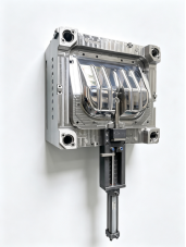
Why Product Shape Should Guide the Mould
The finished shovel decides what the cavity needs to reproduce, not the other way around. A blade may carry a flat centre section, curved edges, a raised rib, or a reinforced neck where it meets the handle, and each of these details changes how the mould is laid out.
A homeowner clearing a driveway after a snowfall doesn't think about mould design, but they will notice if the blade edge feels uneven or if the handle joint flexes oddly under load. Those everyday impressions trace back to choices made in the cavity, so the designer needs to know early on which surfaces stay visible, which ones take repeated stress, and which details must stay consistent from one part to the next.
| Product Feature | Mould Design Consideration |
| Blade surface | Needs a forming area that supports steady flow |
| Curved edge | Requires a matching cavity surface with smooth transitions |
| Handle connection | Needs clear space for accurate forming |
| Reinforcing section | Needs practical material flow without trapped stress |
| Edge shape | Affects both release and later finishing work |
How Blade Shape and Material Flow Work Together
The blade carries much of the visual and functional weight of the product, so its width, curve, and edge profile all need to show up accurately in the cavity. A minor shift in blade shape can change how the plastic moves through the mould and how the finished part comes free afterward.
Because PC doesn't flow as easily as some other plastics, the path the material takes matters quite a bit. A broad blade paired with a narrower handle section creates two very different filling conditions inside the same cavity, so the gate placement and flow path need to work together rather than being treated as separate problems.
A carefully arranged gating layout can shorten the distance the melt has to travel and keep the flow more even across the panel, which can help reduce visible weld lines on the blade face. Designers usually check the gate location, the cavity shape, changes in wall thickness, and how narrow sections connect to broad flat areas before settling on a layout.
How Does Wall Thickness Affect Everyday Durability?
Wall thickness shapes both how the shovel feels in use and how the tooling behaves during production. A blade section that's too thin may flex more than users expect when pushing through packed snow or heavy soil, while a section that's thicker than necessary can slow cooling and use more material than the design really calls for.
The point isn't to make every section match. Different areas genuinely need different thickness depending on their job. A reinforcing rib near the handle joint, for instance, carries different demands than a broad flat blade panel, so the cavity has to accommodate that variation while still avoiding sudden jumps in thickness that make filling harder to control.
| Wall Design Area | General Consideration |
| Blade | Balance between feel, strength, and flow behavior |
| Edge | Should follow the intended shape without restricting flow |
| Handle area | Needs steady support without abrupt thickness change |
| Reinforcing feature | Should connect smoothly into nearby surfaces |
| Transition zone | Gradual change works better than a sharp step |
How Do Draft and Handle Design Affect Part Release?
Once the plastic cools enough, the shovel needs to leave the cavity cleanly, and this step is where a lot of shape-related problems show up. Deep pockets, sharp direction changes, or enclosed features can hold the part against one side of the tooling longer than expected, which risks marking the surface during separation.
Draft angles help with this by giving surfaces a slight lean that lets the part pull away more easily. A blade face and a handle connection often need different draft approaches, since one is broad and flat while the other may involve a socket or opening that needs its own clearance. Skipping draft in favor of a cleaner-looking drawing tends to create problems once production starts.
The handle connection deserves its own attention beyond draft alone, since it's the area that takes repeated force every time someone pushes or lifts with the shovel. A few practical questions help here: how exactly does the handle join the blade, which surfaces around that joint need to stay visible, and can the part pull free from that area without something catching along the way.
Handle Connection
How exactly does the handle join the blade, and does the mould provide enough space for accurate forming?
Visible Surfaces
Which surfaces around the joint need to maintain a consistent appearance after moulding?
Part Release
Can the finished part pull away from the handle area without catching or creating surface marks?
How Do Surface Finish and Gate Position Work Together?
The cavity surface has a direct hand in how the finished shovel looks, and this matters with PC because of its clarity and shine. A smooth cavity surface gives one visual result, while a textured one gives a different feel and appearance, and the choice should match what the product actually needs rather than what's easiest to machine.
Gate position ties into this same conversation. A gate placed without much thought can leave a small mark in a spot that's hard to hide later, or it can force the melt to travel a longer path than necessary across a broad blade. Placing the gate with both flow behavior and finishing in mind avoids creating extra work down the line for a small mark that could have landed somewhere less visible.
What Role Do Venting and Cooling Play?
Air inside the cavity needs somewhere to go as the plastic fills in, and this becomes more noticeable with PC because of the pressures involved in getting a thicker melt to fill completely. Trapped air can leave burn marks, small bubbles, or spots that don't fill all the way, especially near recessed features or along the outer edge of the blade where flow fronts often meet.
Cooling works alongside venting rather than as a separate concern. Broad flat sections cool differently from thicker connection points, and if one area cools faster than another, the part can warp slightly as it settles after ejection. Running cooling channels that follow the shovel's contour, and keeping mould temperature steady rather than letting it drift, helps the material release built-up stress instead of carrying it forward into the finished part.
| Product Area | Cooling Consideration |
| Broad blade | Needs even coverage across the panel |
| Thick connection | May need extra attention to avoid lagging behind |
| Edge section | Needs steady temperature to avoid warping |
| Raised features | Can cool at a different pace than flat surfaces nearby |
How Should Ejection and Mould Structure Be Considered?
Tooling has to keep working smoothly through many cycles, not just produce one correct part. Cavity count, opening arrangement, ejection method, and how easily technicians can reach cleaning points all affect how the setup fits into daily production rather than causing constant small delays.
Ejection features need to match the part's actual geometry. A broad blade area usually needs several support points spread out to avoid pushing on one spot too hard, while smaller features near the handle need more careful placement so they don't leave a mark or stress a thin section. High-precision positioning parts also help keep everything aligned properly cycle after cycle, which matters more the longer a mould stays in service.
Can One Mould Approach Fit Different Shovel Styles?
A household shovel, a garden tool, and a heavier outdoor shovel don't share the same shape or handling needs, so a single cavity concept rarely fits all three well. The blade profile, handle connection, and surface texture usually shift from one product line to the next, and the tooling needs to follow those changes rather than forcing every version into the same layout.
Treating a PC Shovel Mould as part of product development, instead of a separate step handled after the product is finalized, tends to make these adjustments easier to manage. Ongoing communication between product designers and mould engineers helps catch shape changes early, before they turn into costly tooling revisions later.
What Should Be Checked Before the Tooling Enters Production?
A review before manufacturing begins can catch problems that are much cheaper to fix on paper than in steel. This review should look past the drawings alone and consider how the part will actually behave during filling, cooling, opening, and removal.
A practical check usually covers whether the cavity matches the intended shovel shape, how the plastic reaches different areas, whether the part releases without resistance, and whether the ejection layout fits the actual product surfaces.
- Whether the cavity matches the intended shovel shape
- How the plastic reaches different areas of the cavity
- Whether the part releases without resistance
- Whether the ejection layout fits the actual product surfaces
- Whether the cooling layout matches the part geometry
- Whether visible areas match the intended surface finish
- Whether maintenance teams can reach important areas for cleaning
For manufacturers comparing tooling designs across different shovel products, the practical questions come down to how closely the cavity matches the product, how the part moves through each stage of the cycle, and how well the whole setup fits into the existing production routine on the shop floor.
A shovel mould involves much more than reproducing the basic outline of a blade. Product geometry, material flow, wall thickness, draft, gating, venting, cooling, ejection, and surface finish all influence how the finished part performs and how consistently it can be produced.
For PC shovel production, these factors need to be considered together because the material and product structure can affect filling, cooling, stress, and release. A broad blade may require a different approach from a reinforced handle connection, while ribs, edges, and recessed features can introduce their own moulding considerations.
A well-considered PC Shovel Mould should therefore be developed around the actual product rather than treated as a separate tooling step. When product designers and mould engineers review the cavity, material flow, cooling, ejection, and finishing requirements together, potential production issues can be identified earlier and the tooling can be prepared around the way the shovel will actually be moulded.